4 Way 3 Position Hydraulic Valve Diagram Pneumatic Symbols C
Three way valve schematic (to be removed) four-port three-position directional control valve Hydraulic directional valve symbols
Three Way Valve Schematic
How to correctly use a 3 way valve in different applications [16+] hydraulic circuit diagram with check valve, mechanical Way valves two valve spool control three flow four direction ports pressure rotary drawing port hydraulics other mariners repository configurations
4 way 3 position hydraulic control valve working
Pneumatic circuit symbols explained, 59% offValve air parker manual control grainger position way zoom tap Hydraulic system drawing symbolsParker 1/4" manual air control valve with 4-way, 3-position air valve.
Way valve hydraulic position control4 way valve working system diagram in 2022 [diagram] 3 way hydraulic valves diagram3 / 4-way/2-position manual valves on metro hydraulic.

The uses of a hydraulic four way directional valves in a circuit
Image result for hydraulic valve symbolsWay position valve manual remote diagram hydrotools tandem catalog center valves Mariners repository: hydraulics part 1Aro, m series, 4-way/3-position, manual air control valve.
4 way 3 position valve schematic[diagram] 3 way hydraulic valves diagram Explain 4-way-3 position direction control valve used in hydraulicPneumatic circuit symbols explained |library.automationdirect.
![[DIAGRAM] 3 Way Hydraulic Valves Diagram - MYDIAGRAM.ONLINE](https://i2.wp.com/instrumentationtools.com/wp-content/uploads/2016/12/instrumentationtools.com_four-way-solenoid-valve-diagram.jpg)
Directional control valve schematic symbol
Explain 4-way-3 position direction control valve used in hydraulic110v hydraulic valve wiring diagram Valve position way control construction workingHydrotools, hydrotools, 4-way, 3-position remote manual.
Way circuit four uses hydraulic directional valvesHydraulic valve port designations at michael garza blog Hydraulic four-way valvesPneumatic symbols circuit valve position explained solenoid spring double return flow actuated path.

4 way/3 position hydraulic valve working & diagram fully explained with
4 way 3 position control valve working & construction youtube 720p4 way 3 position valve schematic Structure of four-way reversing valve.Position explain.
Valve hydraulic way directional valves four flow control cylinder condition ports classifications lists table someValves way position manual window close metrohydraulic equipment [diagram] piping diagram 3 way valve[diagram] 3 way hydraulic valves diagram.


Three Way Valve Schematic

Mariners Repository: Hydraulics Part 1 - Direction Control Valves
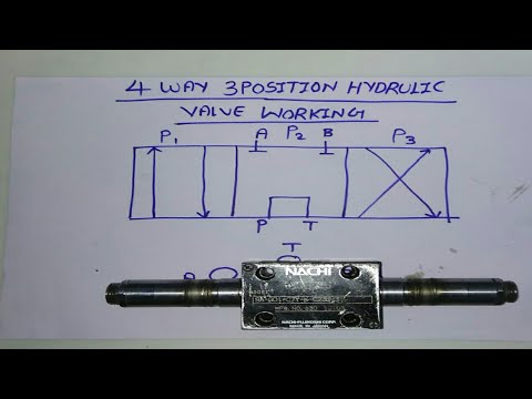
4 WAY 3 POSITION HYDRAULIC CONTROL VALVE WORKING - YouTube
![[DIAGRAM] 3 Way Hydraulic Valves Diagram - MYDIAGRAM.ONLINE](https://i2.wp.com/az417944.vo.msecnd.net/diagrams/manufacturer/simplicity/simplicity/garden-tractors/power-max-series/1690230-9020-19-5hp/dual-hydraulic-valve/diagram.gif)
[DIAGRAM] 3 Way Hydraulic Valves Diagram - MYDIAGRAM.ONLINE

Pneumatic Circuit Symbols Explained, 59% OFF

4 Way/3 Position Hydraulic Valve Working & Diagram Fully Explained with

4 Way 3 Position Valve Schematic

The Uses of A Hydraulic Four Way Directional Valves in a Circuit
